Michael Posner
I currently work as a System Software Engineer. I earned a Masters degree in Robotics as well as Bachelors degrees in Computer Science and in Mechanical Engineering from the University of Pennsylvania. My interests include robotics, embedded systems, aerospace, machine learning, artificial intelligence, distributed systems, and data analysis.


Robockey
For my Mechatronics class final project, we worked in teams of three to create a team of autonomous hockey-playing robots using microcontrollers, IR phototransistors, Wiimote IR cameras, wireless modules, motors, and whatever we could find.
The Game
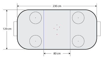
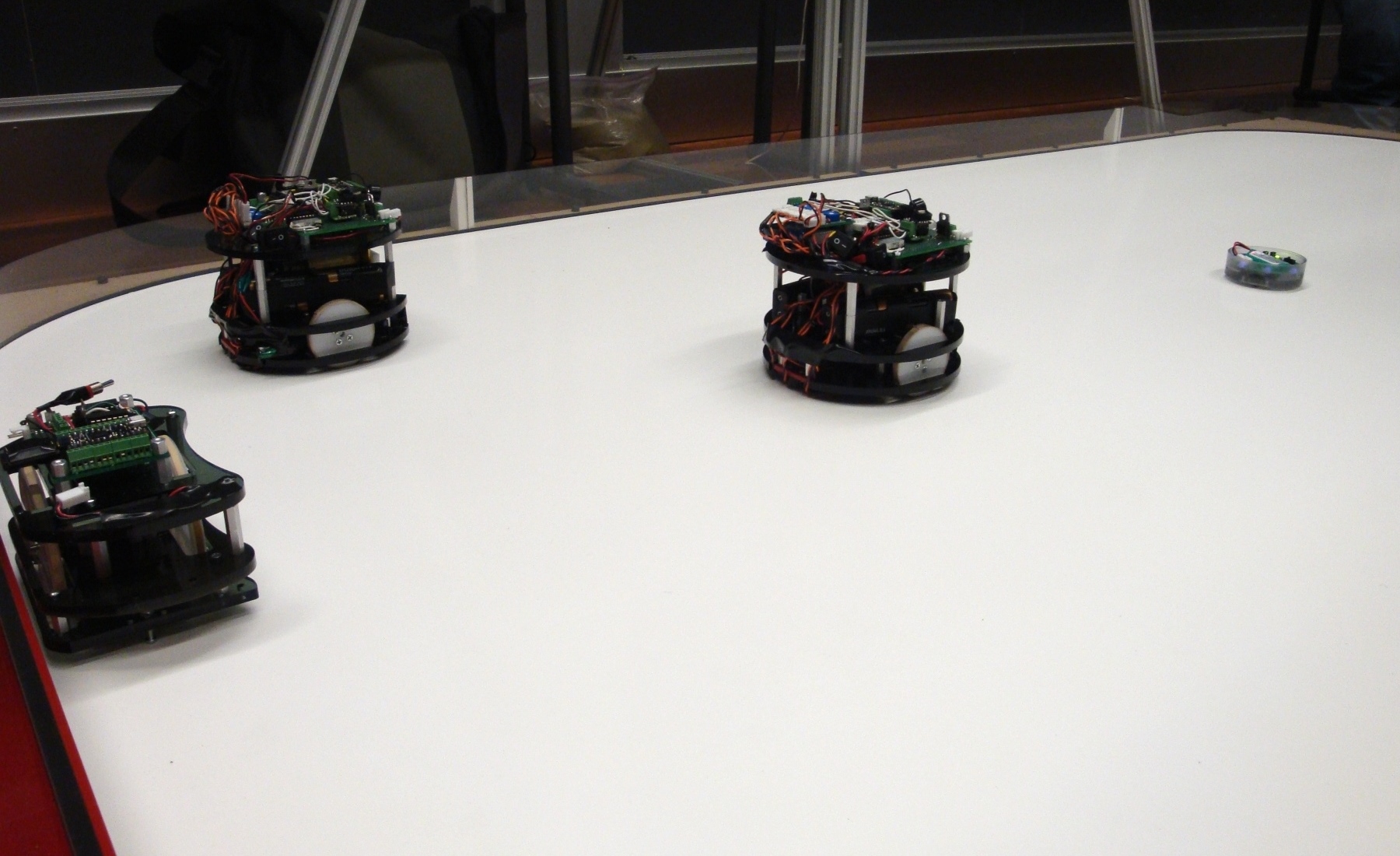
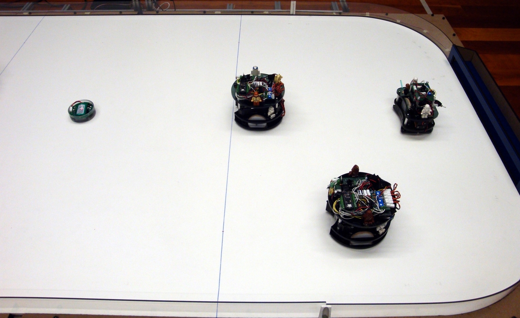
Two teams face off in a rink approximately 2 meters by 1 meter in size. Each team fields three robots which must fit inside a 13 cm-tall cylinder with a diameter of 15 cm. A goal is scored if the puck crosses the opposing team's goal line. Play is divided into two one-minute halves, with halftime and timeouts lasting 30 seconds each. If the score is tied at the end of regulation, another half is played following a second halftime, and if play is still tied a best-of-three shootout decides the winning team.
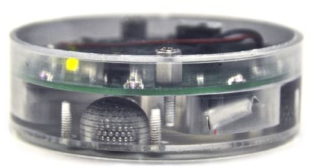
Two key elements of the rink are augmented to assist the robots. First, the puck consists of a clear plastic cylinder 7 cm in diameter and 3 cm high. Inside the puck there is a ring of equally spaced IR LEDs. The robots use this IR light to locate the puck. Second, there is a constellation of 4 IR LED clusters hung 5 meters above the center of the rink. The robots use this cluster to locate and orient themselves on the rink.
Design
We decided to create two forward robots and one goalie robot. The forward robots would have all sensors and equipment necessary to play the game. The goalie robot would be different in that it would drive side to side in front of the goal and seek to place itself in front of the puck.
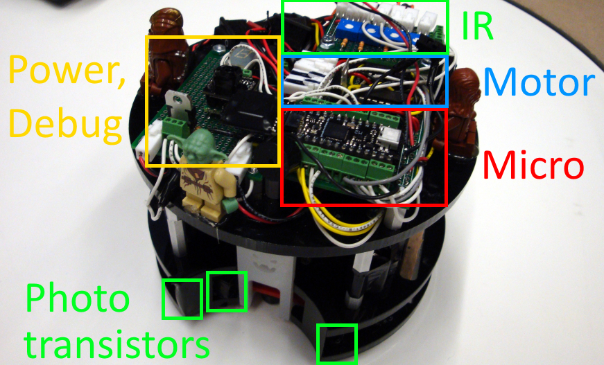
In order to find the puck, we needed to place IR phototransistors on our robots. We used three phototransistors, one on each side of the robot and one facing forward. This allowed us to narrow down the puck's location by observing the difference in signal strength between the left, right, and center phototransistors and adjusting our heading to keep the puck in front of the robot.
In order to detect when the robot had successfully collected the puck, we had originally planned to use limit switches placed in the front of the robot. The rules stated that the robot could not enclose more than 20% of the puck's area when viewed from above, so this limited our options for detection and transportation. After some testing we determined that the constant switch bouncing that would occur as the robot pushed the puck would make it difficult for software to accurately determine whether the robot was still in control of the puck. We decided to add another phototransistor in the front of the robot that was angled inwards towards the body of the robot and shielded. This would prevent false triggering of the phototransistor when the puck was not close to the robot, but give us a more reliable mechanism to detect whether the robot was in control of the puck.
Unlike regular hockey, shooting the puck was not a necessary component to this game. Many teams relied on simply trying to push the puck into the goal. However we decided early on that to make it more fun we would try to give our robot the ability to shoot the puck. We settled on using a solenoid because of its speed and the force we would require to shoot the puck. We quickly discovered that the puck was quite heavy and we would need large solenoids in order to shoot. We dedicated the lower center of our two forward robots to solenoids.
Another important part of this competition was the choice of robot size and weight. Some teams chose to design robots that were very light and fast. Our team chose to do the opposite, and build a heavier robot that would hold its ground better. The large solenoid and multiple batteries helped keep us from being pushed around and gave our wheels better traction.
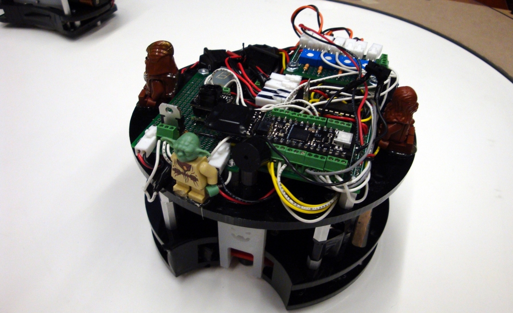
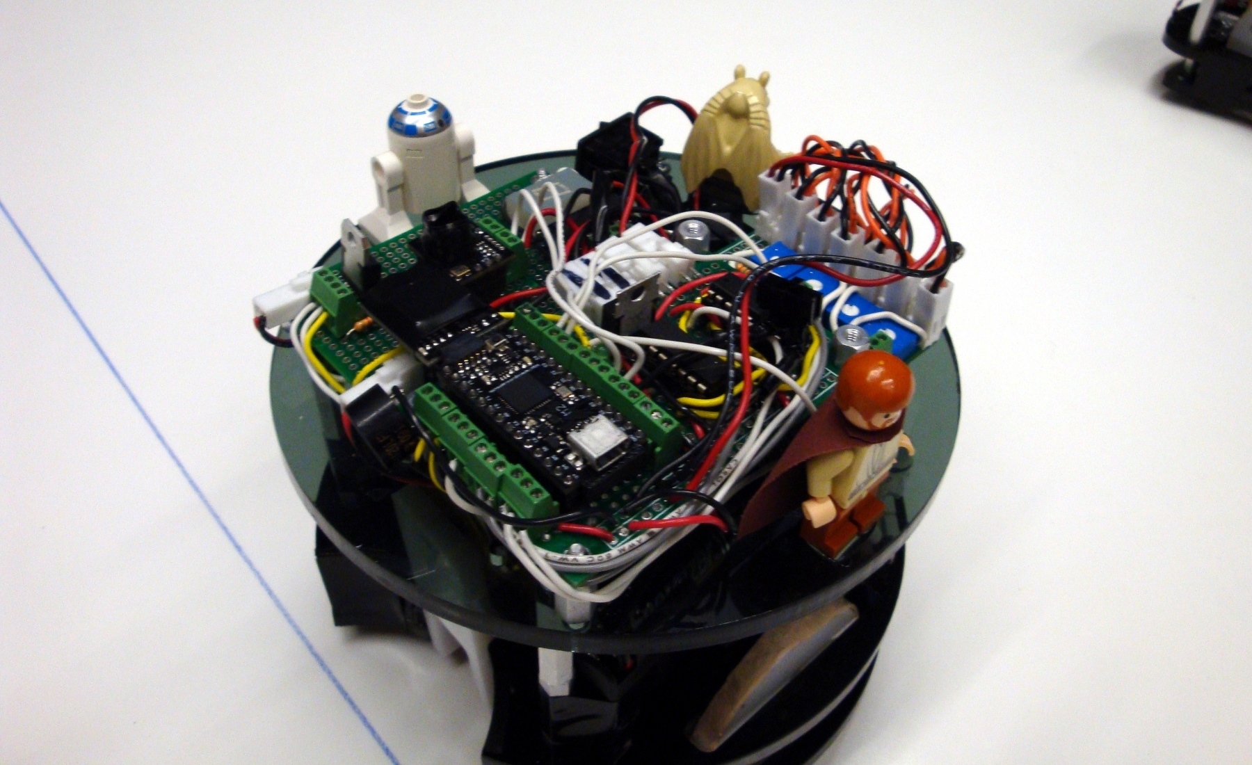
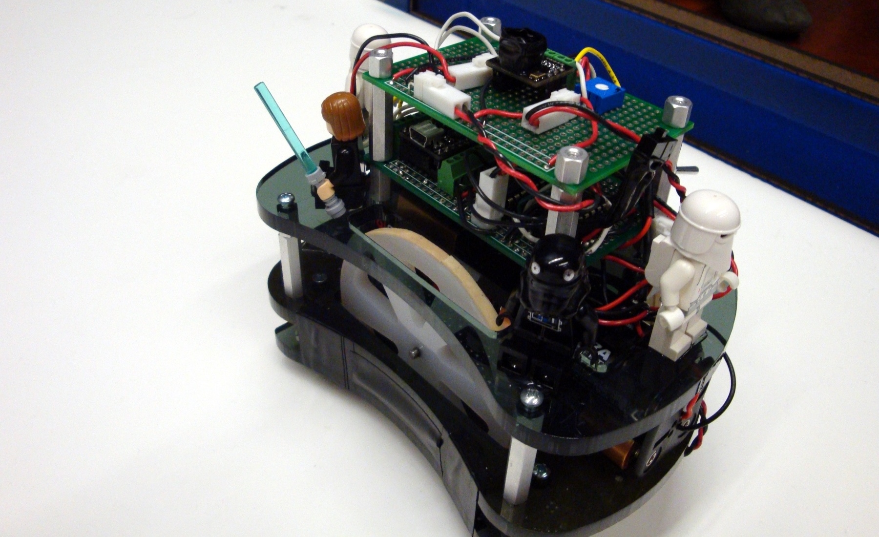
After designing all of our robots with SolidWorks, we used the school's laser cutters to create them. The robots consisted of several layers of laser-cut acrylic, connected with bolts and standoffs. We went through several iterations of laser-cut designs as we adjusted the mounting and fit of various components. We also fabricated the wheels out of acryclic, and added rubber bands to the edges for traction.
Electronics
We soldered together our own motor driver boards and phototransistor circuits onto perfboards. We used potentiometers in the phototransistor circuts so that we could easily tune the sensitivity of the phototransistors. This is important because the amount of ambient IR light present in the environment had a significant impact on their measurements. The phototransistors had to be adjusted when switching from a dark room to a bright room and even between daytime and nighttime. We also added several switches and wired up an 8 segment display to our robot to help aid in debugging our code.
Since we wanted large solenoids in order to shoot the puck, this meant that our solenoids would have to be high voltage (~12V), which also implied that they would draw significant current. These requirements led us to choose LiPo batteries to power the solenoids because of their high discharge rates. The LiPo battery was separate from the main power system on the robot, which consisted of two packs of 6 AA batteries. These batteries supplied sufficient power to the microcontroller and sensors as well as the motors.
Software
The robot software is organized into a state machine. At its core the main states are Stop, Find Puck, Find Goal, Shoot, and Team Override. A typical progression would be:
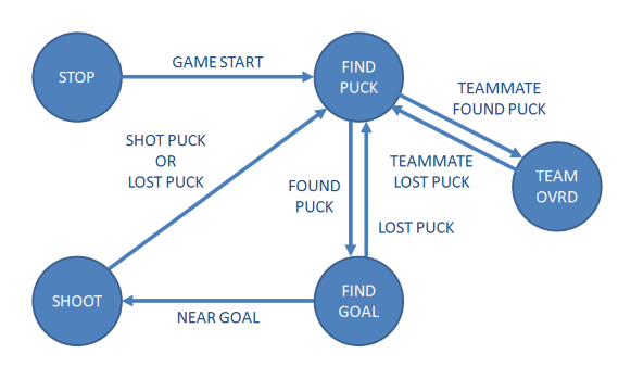
- Stay in Stop mode until signaled that the game has begun
- Go to Find Puck mode and search for the puck
- When the puck is acquired, go to Find Goal mode and drive towards the goal
- Once we are within goal distance, Shoot the puck
In addition to this state machine, the microcontroller is constantly updating data from its sensors and checking for new messages from the wireless module. A new wireless packet could be a command packet, signalling the robot to stop for halftime or to detangle from another robot, or it could be a teammate packet from another of our robots. These teammate packets indicated that the other robot has found the puck and that instead of possibly getting in the way of the other robot, this robot should move towards the goal on the opposite side of the rink from its teammate to aid in goal scoring.
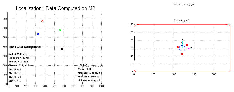
One of the most complex parts of the software is the section that determines the robot's position and orientation on the rink. Here, the IR camera from a Wiimote is used along with a supplied interface board to provide the microcontroller with the coordinates (in pixel space) of IR light sources along with their perceived intensity. Using this information along with the known dimensions of the IR constellation, the localization code calculates the distances between the light sources to map the perceived pattern to the reference constellation. It uses this information as well as a scaling factor to calculate the orientation and position of the robot on the rink.
Because of the complexity of these and other mathematical operations, as well as the nature of running embedded code, our team created a debug program to aid in troubleshooting our robot software. This program was written in MATLAB and runs on a computer that is connected to the microcontroller via a USB serial interface. This program not only includes robot routines to print debug information to the computer program's console, it also visualizes data sent from the robot in a real-time virtual representation of the rink.
Results
The matches we played consisted of a series of friendly matches followed by several ranked bracket-style matches. Our robots did relatively well orienting themselves on the rink since we devoted so much time to our localization code and our debugging system. As the matches continued we discovered that one of the things we had to tweak most often about our robots was the group of IR phototransistors used to detect the puck. We often had to adjust their sensitivity and eventually tried to shield them around the edges from other light sources by creating hoods for them out of tape. If we could start over again, we would probably try to devote more time to create a more robust puck finding system. We also discovered that our goalie would slowly begin to drift away from being parallel with the goal as he tried to move back and forth. This was due to being bumped but also due to the inevitable occasional slip of one wheel relative to the other on the rink. We could have improved our goalie to detect this and correct itself. The robots also did a good job of staying out of each other's way because of our team override code we added. This prevented us from sabotaging ourselves several times and gave us an advantage over other teams.
In the final bracket our team did very well, placing in the top 8 out of 25 teams (we lost in the quarterfinals). Below you can find additional photos and video from our tournament games.
Tournament
