Payload System
Drift Model
The payload drift model is based on a linear
approximation of drift used in military
applications [example]. The model takes into account the
altitude of the drop and the velocity of the wind in
both the longitudinal and latitudinal directions. It
can be formulated as  . We
first calibrated the model using real test data to find the drift
coefficient, K, which is a function of the parachute and
payload parameters. Once the drift coefficient was
found, the model can be used to calculate the drift of
the parachute in each direction.
. We
first calibrated the model using real test data to find the drift
coefficient, K, which is a function of the parachute and
payload parameters. Once the drift coefficient was
found, the model can be used to calculate the drift of
the parachute in each direction.
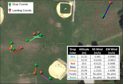
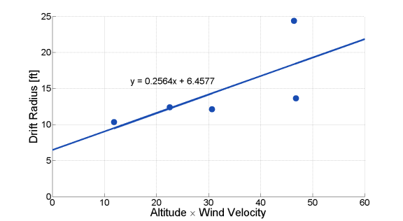
Five different test payload drops were conducted to determine the drift coefficient. A map of these test drops is shown on the left below. These test drops were conducted under various wind speeds and resulted in a wide distribution of drift radius. The plot below right shows the linear relationship between drift and the product of wind speed and altitude, the slope of which is the experimental drift coefficient (K = 0.2564). This plot is obviously sparse and we would have liked to collect more data if we had the time for more flight tests. We also wish we had the time to validate this drift model with additional drop tests.
Wind Data
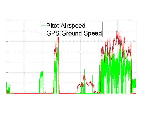
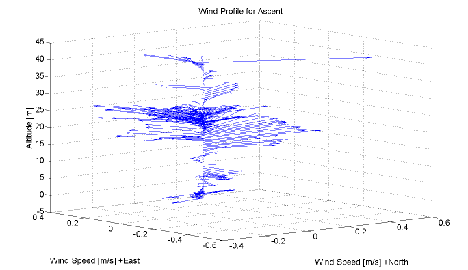
To integrate the drift model into our payload drop process, we need to provide it with some data, namely the wind velocity as well as altitude of the drop. To obtain the current wind speed on the aircraft, we calculate the difference between the GPS ground speed and the airspeed as measured by the Pitot probe (see example below left). This wind speed data is recorded with GPS heading data during the entire ascent of the aircraft, creating a 3-dimensional wind profile of the ascent (see example below right). Once a constant cruise altitude is reached, the average wind speed in the East-West and North-South directions is used to calculate the drift the parachute is expected to undergo in each direction according to the linear model.
The target location is then offset by the magnitude of the drift component in each direction to obtain the final drop location. This is the location the airplane should drop the payload so that it will drift to the original intended target location. This drop location becomes the airplane's new destination. Once the airplane reaches the location, the payload release mechanism is activated to release the payload.
Release Mechanism
We iterated through several different designs for our payload release. Most designs involved servos either dropping dispensable doors or un-hinging compartments. The payload release mechanism was also influenced significantly by our choice of aircraft. When we were thinking of using the Raven RQ-11, we had much more room to design in than with the SuperCub. In the end, we went with a simple servo mechanism that released a hinged door, due to the space constraints of the Supercub.
