Software
ArduPilot Mega Arduino
As previously mentioned, we have chosen to use a custom Arduino board called the ArduPilot Mega as our microcontroller. The ArduPilot project actually has a software and code solution as well, but we decided to write our own code for the board. Since the ArduPilot project is meant to be a general solution package for many platforms (RC airplane, quadrotor, helicopter, etc), its code is inherently large and complex. In addition, it is not well documented. We wanted to make sure we understood everything that occurred on the board, and so we wrote our own code to better meet our specific needs and be easier to tweak as we tried different control schemes. We did keep the sensor libraries for reading data from the sensor shield as these would have been difficult to replicate, are unique to this board implementation, and are not the focus of our project. We also hacked and incorporated the ArduPilot code so that we could use the ArduPilot Mission Planner software to download the contents of the flash memory logs to a computer.
Our Arduino code consists of three main loops that run at varied intervals. This is because timing is important for our application, and so we didn't want to bog the board down with unnecessary calculations. The slow loop runs at a frequency of 5 Hz and is responsible for reading sensors such as GPS and barometer that take longer to update, as well as running components of our code that are not speed-essential like the navigation loop. The medium loop runs at a frequency of 25 Hz and is responsible for updating more essential sensors such as the accelerometer, gyroscope, magnetometer, and Pitot probe. This loop also runs portions of our algorithm such as our controls inner loop and wind profile generation. The fastest loop runs at the full speed of the board and is responsible for dictating when the other loops run, updating the plane's current orientation estimate, reading RC commands and sending servo commands. There are also loops that transmit telemetry data and log data in the on-board flash memory that run at 5 and 15 Hz, respectively.
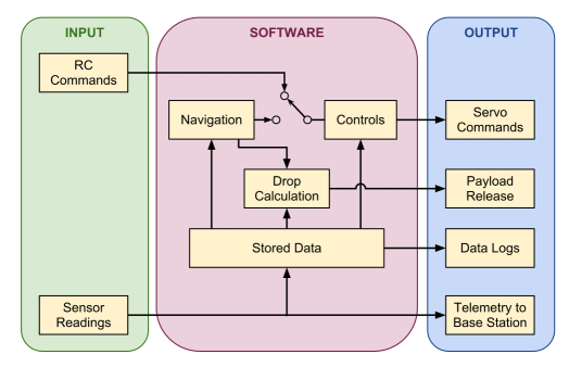
In manual mode, the software reads signals from the RC input. These signals are then passed to the controls functions, which use the RC signals along with current sensor data regarding GPS location and heading, plane orientation and speed in order to figure out what commands need to be sent to the throttle, rudder, and elevator to keep the airplane flying along the desired course. In autonomous mode, the command signals are generated from the navigation code instead of read from the RC input.
In addition, the software determines when to release the payload using the plane's GPS coordinates, logs data to the onboard flash memory, and sends data via the XBee tranciever to the laptop on the ground for real-time plotting and additional backup logging.
Telemetry MATLAB
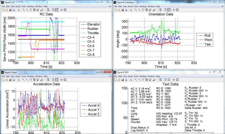
A MATLAB script was written in order to receive and process telemetry data transmitted from the airplane. This allows a wide variety of sensor data and other information to be viewed through real-time text and graphs. This is important to make sure that the system is correctly functioning before a flight test as well as to see how the plane is reacting to pilot or controls changes during flight. The script reads in data using a serial protocol over USB from the ground XBee module and processes it for display. The graphs display the data in a moving window of 30 seconds, but the script also logs data to text files (in the same format as the on-board logging) in order to provide a backup method of data collection in case of failure of the on-board logging system. A sample telemetry output can be seen on the left.
Data Analysis MATLAB
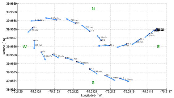
A second MATLAB script was implemented in order to process flight data from either the flash memory logs or the telemetry logs. This script generates a wide variety of graphs, from sensor and RC data to the state of the navigation and controls algorithms at all times during the flight. This enables flight data to be reviewed in detail at a later time in order to gain information about how the plane reacted and how the software performed so that adjustments can be made. At left is an example GPS output of a flight, depicting GPS position, heading and speed at one second intervals.
Code Documentation
Our complete Arduino code and documentation can be found here.
